Disclaimer
This post assumes readers already understand fundamental Wi-Fi design concepts outlined in the Certified Wireless Design Professional (CWDP) curriculum. It focuses on how those concepts evolve and adapt to large-scale deployments.
Challenges of Design at Scale
WiFi design—the placement of access points—is the foundation for delivering a reliable network experience. To build an effective design, one must understand network requirements, device counts, throughput needs, building materials, and physical and virtual constraints on hardware installation. Site surveys and stakeholder meetings provide important details used in wireless design tools.
These fundamentals remain the same regardless of scale. The primary challenge at large scale is managing hundreds of sites, often spread worldwide, making it impractical to survey every site or meet all stakeholders directly. These sites often include retail stores, distribution centers, and remote offices, each with unique constraints that shape the design.
The key to tackling scale is not to focus on the differences between sites, but to take a counterintuitive approach and find the similarities across them. Any company that has successfully scaled did not do so by treating every building or site as unique. Instead, creating standard templates lies at the heart of business expansions.
While there may be multiple templates, hundreds of sites can ultimately be grouped into just a few categories. These templates might be based on factors such as the size of the location, the nature of the business conducted there, or other criteria specific to the organization. Regardless of the basis, templates always exist.
The first task is to identify how many “types” of sites there are instead of counting “how many” individual sites. After establishing these categories, the next step is to hold stakeholder meetings focused on understanding the key requirements for each site type.
Site surveys should be performed on at least one location of each site type to analyze floor layouts, building materials, areas of high user density, critical business application zones, and other relevant factors. This approach enables the creation of scalable designs that address the needs of multiple sites efficiently.
Cookie cutter designs often receive criticism for being either over-engineered or under-engineered, both of which can result in suboptimal network performance. However, the key to making things work at scale is to build the most efficient cookie cutter designs. The goal should be to develop standardized a.k.a cookie cutter designs that balance efficiency, cost, and performance—designs that can be consistently deployed across many sites without compromising the user experience.
Easier said than done isn’t it?
Creating Optimal Cookie Cutter Wireless Designs That Work
The best approach to creating Wi-Fi designs for large-scale deployments can be attributed to a quote from Abraham Lincoln:
“If I had six hours to chop down a tree, I’d spend the first four sharpening the axe.” You’ll understand why by the end of this blog.
Start by analyzing floor plans and identifying key work streams with unique connectivity requirements. This means assessing user density, client device counts and types, the nature of the applications in use, and identifying the stakeholders who can provide critical information. All of this groundwork should be done before setting foot on-site for a survey walkthrough. Arriving at a site survey well-prepared and informed will make data collection more efficient and focused, allowing for a stronger design.
The workstreams and use cases identified before the survey will often shape the specific tasks requiring attention during the site visit. For example, some areas may have stationary desktops with wireless cards—devices that don’t roam but demand high throughput. Other areas could see constant roaming from handheld devices but have modest throughput requirements. There are countless variations, and recognizing these ahead of time will allow for more targeted data collection.
During the site survey, several tasks are essential:
- Identify wall locations, types, and attenuation levels.
- Assess possible AP mounting methods while noting building constraints.
- Document unique challenges for each workstream, including roaming needs, throughput levels, and required application SLAs.
These fundamentals remain consistent at any scale. Up until this point, designing WiFi for a single site or many follows the same best practices. However, once the survey data is in hand and analysis begins, the approach diverges from traditional “best practices” .
In large-scale projects, a sustainable solution comes from using what can be called “grid patterns” for AP layouts. This means applying standard formulas or guidelines to group similar workstreams and requirements. For instance, in a retail context, merchandise, grocery, and checkout zones may be grouped together, allowing for a repeatable access point grid—such as installing APs in a 50 ft x 50 ft pattern across those areas. Specialized zones, like high racks, might warrant a directional antenna and a custom pattern, but such areas also often follow consistent layouts across multiple sites.
The fewer repeatable patterns used in the design, the more scalable and easily managed the deployment becomes. Is this approach over-engineered? In some ways, yes. But a cost-benefit analysis typically reveals this as an optimal use of resources—streamlining installation, cabling, switch planning, and ensuring the network can flexibly address both current and foreseeable needs.
For example, even if the checkout area requires 100 scanners and the grocery zone currently has no client devices, the same standardized pattern for both zones might introduce some interference and suboptimal cost of deployment but it ensures future coverage if digital displays or new IoT devices are later introduced—saving considerable time and money on redesigns or retrofits in the long run.
Of course, “over-engineering smartly” depends on balancing cost with sound requirement analysis. It isn’t about adding capacity everywhere, but rather sizing for grouped, real-world needs, as informed by thorough stakeholder meetings and up-front planning. This is exactly why the “sharpening the axe” quote makes sense in large-scale WiFi design. Investing time in up-front analysis, requirement gathering, and template planning ensures that the site survey and subsequent design steps are efficient and effective.
Now that the site survey is complete and all necessary information is collected, the next challenge is scaling the solution. My approach breaks this process into three deliberate steps:
1. Proof of Concept (PoC):
Suppose there are 500 sites matching a specific template. The first step is to pick a single site to serve as the proof of concept for the new design. At this stage, an overbuilt, over-engineered wireless network is not just acceptable, but preferable. The PoC environment should offer the flexibility needed to experiment—turning APs on and off, changing configurations, and studying design performance across different scenarios.
At scale, it’s often impossible to control every client device type on the network. At a minimum, focus PoC testing on your controllable devices—especially corporate laptops, handhelds, or specific IoT equipment—to ensure the least/most capable/important devices perform as expected while stationary and roaming. Run intended applications on representative devices in both mobility scenarios and involve stakeholders in real-time testing, so they can confirm that network performance meets their needs throughout the process.
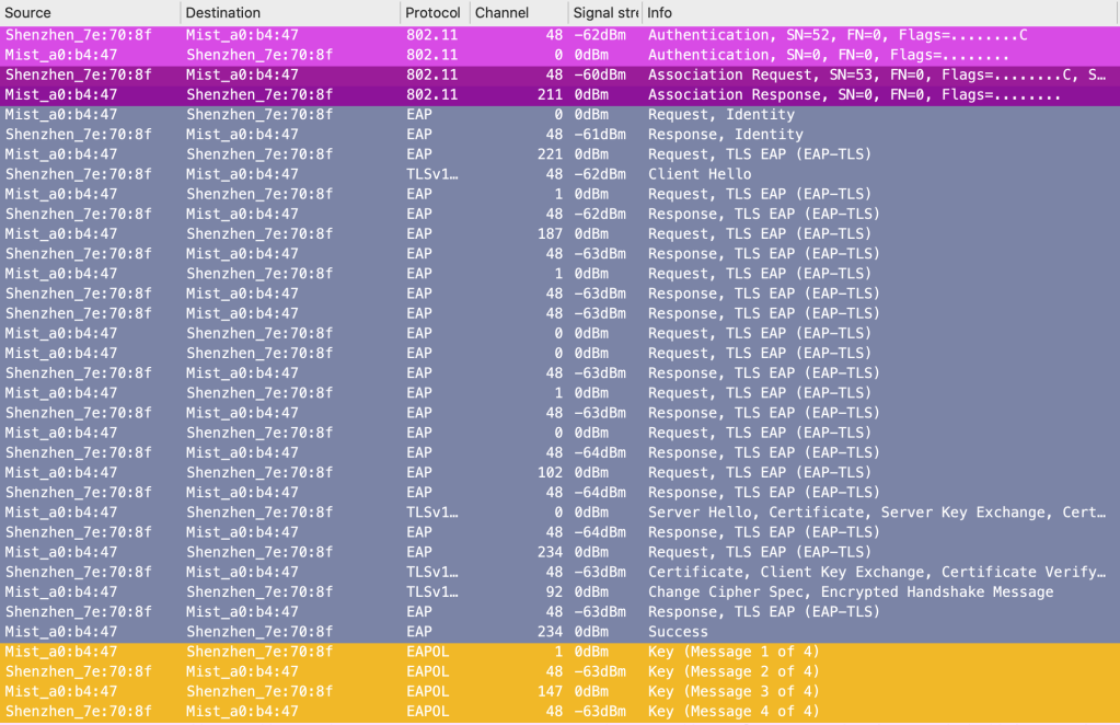
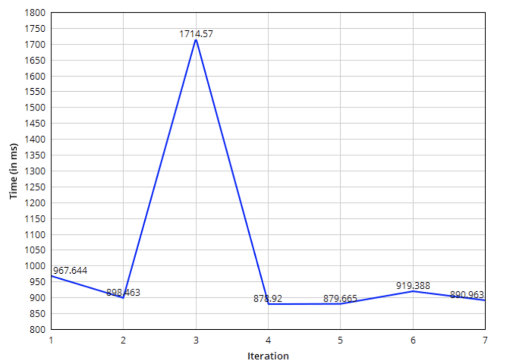
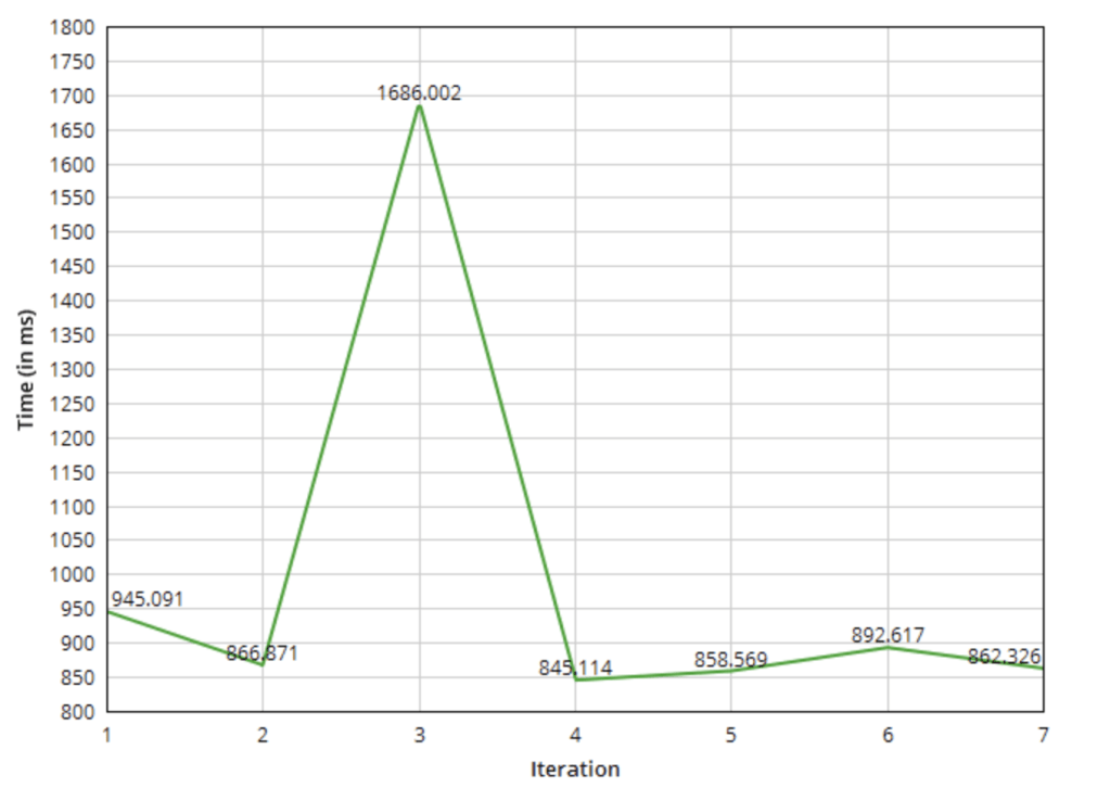
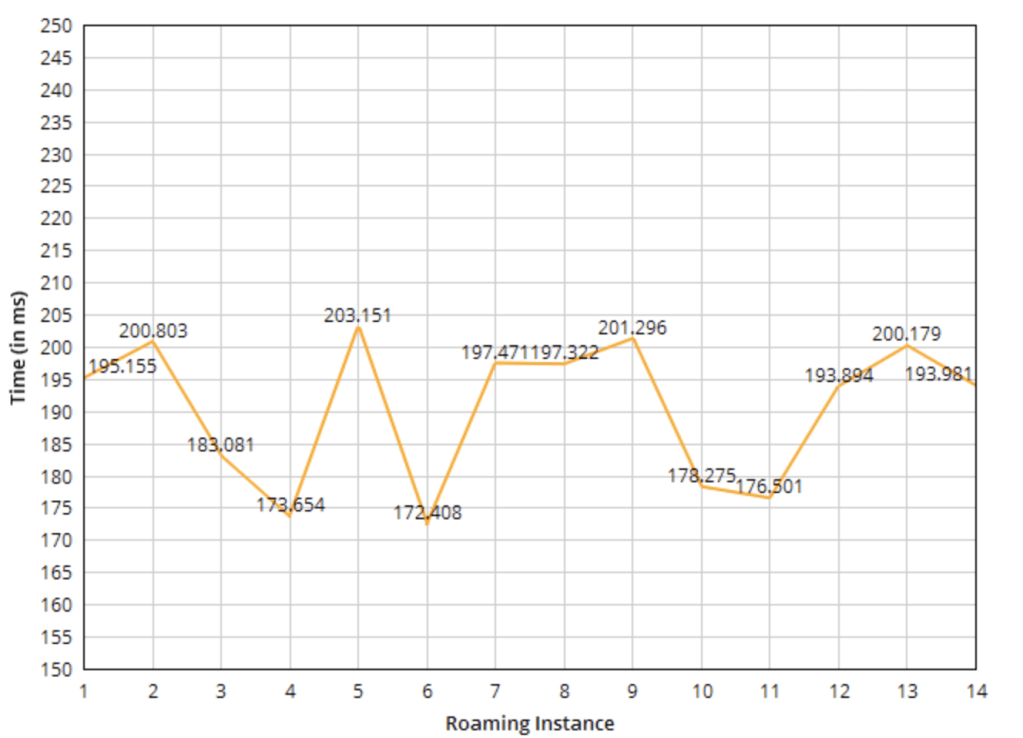
KPIs to monitor during the PoC can include:
- Channel utilization
- Client count distribution across APs
- Connection/roaming success and failure rates
- RSSI (signal strength) levels for client devices
Depending on the complexity of your network and vertical, this list may be longer—additional KPIs could include measurable application throughput, latency, and packet loss, as well as error rates for specific device types.
The goal of the PoC is to rigorously test and ensure the most optimal cookie cutter design possible for real-world demands, not to save costs or move quickly. Only once all critical applications and devices perform as required, key stakeholders sign off, and metrics consistently meet or exceed defined targets should the project be considered ready to move on to the Pilot phase. This iterative approach allows for fine-tuning grid layouts and coverage, leading to a highly optimized cookie cutter design.
2. Pilot:
With an optimized design in hand, the next phase is pilot deployment across a diverse group of sites—typically five to ten, depending on overall scale. The goal here is to expose any remaining variability between sites, such as unexpected differences in building construction or ceiling heights due to local regulations. By piloting in geographically and structurally varied locations, you can verify whether the template design holds or if adjustments are needed. This phase is critical for identifying edge cases and ensuring repeatability before moving to mass deployment.
During the pilot, ensure that KPI performance at each site aligns with what was observed in the PoC phase, making adjustments as necessary if discrepancies appear. It is essential to catch and address issues at the PoC or pilot stage, as these phases are designed to test your design assumptions under real-world conditions. Sometimes, unexpected problems may challenge your original assumptions—embracing these discoveries early on allows for refinement and prevents costly errors at scale. Failing fast and iterating in the pilot phase leads to a robust, scalable deployment, ensuring efficiency and minimizing surprises during mass rollout.
At this stage, much of the stakeholder conversations are with install teams and vendors who will ultimately be responsible for large-scale deployments. Gather their direct feedback on the pilot process, including what worked well and what obstacles or inefficiencies they encountered. This candid input can reveal practical issues that might otherwise go unnoticed, from hardware compatibility concerns to logistical bottlenecks. Documenting both positives and negatives from these stakeholders ensures that lessons learned are incorporated before General Availability, leading to smoother and more successful future rollouts.
3. General Availability (GA):
After validating the design through PoC and pilot testing, the solution moves to general availability. This is where thorough documentation and runbooks become indispensable. Detailed installation guides should specify part numbers, bracket types, mounting heights, access point orientation, and any other requirements to minimize field errors.
This documentation must include feedback from install teams and vendors collected during pilot deployments. Their insights reveal practical deployment challenges and efficiencies that improve the guides for real-world conditions. Incorporating this feedback reduces mistakes, builds installer confidence, and speeds up deployments, resulting in predictable and successful large-scale rollouts.
Summary
The path to successful large-scale WiFi deployments lies in:
- Strategic thinking about scale – Focus on similarities, not differences between sites
- Systematic validation – Use the three-phase approach to thoroughly test before broad deployment
- Standardization with flexibility – Develop grid patterns that can accommodate reasonable variations
- Documentation and process – Create clear runbooks that enable consistent execution
Spend ample time “sharpening the axe”—gather requirements, analyze site types, and test thoroughly with PoC and pilot stages. Only after rigorous testing and validation should you roll out the design broadly, armed with the right tools and knowledge for success.